Looped vs Dead-End Watermains in Ontario: What a Development Plan Must Actually Demonstrate
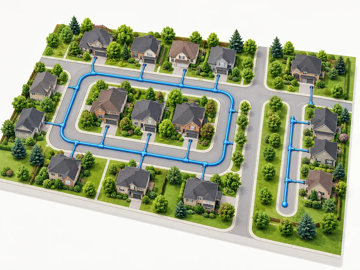
A watermain layout can look straightforward on a drawing. One arrangement forms a connected loop around part of a development. Another extends along a road or site corridor and ends without a continuing connection.
These patterns are commonly described as looped and dead-end watermains.
But the shape of the line on a plan is only the starting point.
A loop does not automatically prove adequate water pressure, fire flow, available capacity or uninterrupted service. A dead-end arrangement does not automatically establish that a development is unacceptable.
For an Ontario project, the meaningful comparison depends on the real network connections, operating conditions, development phases and applicable authority requirements.
1. What makes a watermain looped?
A looped watermain connects back into the distribution network, providing connected routes through a portion of the system.
In a simple concept, a development might have connections at two locations with a route between them.
Larger water distribution systems can contain multiple connected loops, grids and branching sections. They do not necessarily resemble a single ring.
The key is to identify the actual connections.
A useful plan should distinguish:
Existing infrastructure from proposed infrastructure.
Confirmed connection points from possible future tie-ins.
Connected routes from terminating branches.
Infrastructure within the project scope from work controlled by others.
Two routes may also share a common upstream segment.
That means a local loop can offer a different path around one segment without creating two fully independent sources of supply.
The engineering assessment should describe the specific benefit supported by the network evidence.
2. What is a dead-end watermain?
A dead-end watermain terminates rather than continuing through another network connection.
It may be part of an established distribution arrangement or an interim condition before later development connects the main elsewhere.
These two situations need different explanations.
For a permanent dead end, the project team must assess the intended long-term arrangement and the applicable operator requirements.
For an interim dead end, the team must also explain how and when the arrangement is expected to change.
A line marked “future connection” does not mean that connection is available during the current phase.
The submission should identify what will operate before the later work is complete.
It should also record any unresolved dependencies, such as a connection across neighbouring land or infrastructure associated with another development.
3. Compare the same development conditions
A meaningful layout comparison should use consistent assumptions.
It would be misleading to compare a completed loop serving an entire development with a dead-end branch serving only its first building and treat the difference as purely a matter of network geometry.
The team should compare defined alternatives under the relevant development conditions.
Question Looped arrangement Dead-end arrangement
Connectivity Which connected routes are actually available? Where does the main terminate?
Segment isolation What route remains under the assessed scenario? Which users depend on the affected segment?
Operations What arrangements require operator coordination? What terminal operating provisions are required?
Development phases When are the connections completing the loop available? Is the terminal condition interim or permanent?
Performance What does the engineering assessment establish? What does the equivalent assessment establish?
This table is a comparison framework, not a design-selection rule.
The applicable engineering criteria and responsible authority determine what the project must demonstrate.
4. What Ontario guidance says about looping
Ontario's drinking-water design guidance discusses loop, grid and tree distribution configurations.
Its discussion of distribution layouts favours practical tie-ins and looping to reduce dead ends, improve reliability and address stagnation concerns.
Where dead ends cannot be avoided, the guidance discusses appropriate flushing provisions.
However, general guidance should not be mistaken for an automatic project approval.
The applicable requirements may depend on the municipality, system owner and nature of the proposed work. Local or regional criteria may be more stringent.
Ontario's Watermain Design Criteria also apply within a defined drinking-water works permit context. They should not be presented as universal authorization for every private pipe or development connection.
For a specific project, the design team should identify the governing documents, reviewing authority and operator requirements.
“Looping is generally preferred where practical” is not the same conclusion as “this proposed loop is acceptable.”
The second statement requires project-specific evidence and review.
5. A connected loop is not proof of capacity
One of the most important distinctions is between network connectivity and network performance.
Connectivity describes the routes through which water may move.
Capacity assessment considers the proposed demand and the relevant network conditions.
A looped layout may affect performance, but the drawing alone cannot establish how the receiving system will respond.
For example, a proposed development might have room for a second connection while the upstream supply conditions remain unresolved.
That is a potentially useful layout opportunity, not a completed capacity demonstration.
Similarly, a pressure observation taken under one condition does not automatically establish performance for every relevant operating scenario.
Domestic demand and fire-protection needs must be assessed using appropriate project inputs and criteria.
The civil servicing concept, supporting analysis and building-services information should describe the same proposed development.
This article does not prescribe pipe diameters, fire-flow requirements or hydraulic calculation methods.
6. Understand what redundancy means in the actual network
A connected loop can provide an alternative route around a particular isolated segment.
However, the benefit depends on which segment is unavailable and what connections remain usable.
Suppose a development has two apparent connection points.
The routes might return to a shared upstream main.
The loop could still offer a useful local routing benefit, but it would not automatically eliminate the shared upstream dependency.
To evaluate the arrangement, the responsible professionals should identify the relevant isolation scenario and trace the network beyond the site boundary.
A claim about one local segment should not be expanded into a promise of uninterrupted supply under every event.
Water-system operating decisions also belong to the responsible utility or system operator.
Property owners should not manipulate public valves or hydrants to test a proposed layout.
7. Show the interim and ultimate development phases separately
Phased developments often create the greatest risk of misunderstanding.
The ultimate site plan may show a complete loop, while the first phase connects at only one location.
Until the later connection becomes available, the first phase may operate as a dead-end arrangement.
A useful servicing submission should show the network state for each meaningful development stage.
It should explain:
Which connections are available for the first occupied phase.
Which works are needed to complete the ultimate loop.
Whether those works are within the applicant's control.
What authority or operator input is needed for the interim arrangement.
What happens if the second connection is delayed.
An expected future date should not be treated as a confirmed connection.
If the development programme changes, the team should revisit the relevant servicing assumptions.
The goal is to identify the actual arrangement serving each stage, rather than relying on an ultimate drawing that does not yet describe the operating system.
8. Check land access and route feasibility
A proposed loop needs a feasible physical route.
The drawing should account for roads, buildings, utilities, landscape areas, property boundaries and other constraints.
A route crossing land outside the applicant's control may depend on access agreements or other permissions.
An engineering drawing does not grant those rights.
The shortest route on paper may also cross a constrained corridor, while a longer alternative could involve different coordination requirements.
These issues should be recorded before the team presents a preferred layout as settled.
Likewise, a proposed tie-in should be identified as confirmed, subject to investigation or dependent on third-party work.
A feasible corridor and a confirmed network connection are different things.
9. Prepare a reliable information package
Before requesting a watermain layout comparison, gather the current site plan and available network information.
Useful inputs include:
Property location and municipality.
Latest development concept and survey.
Available water distribution records.
Existing servicing reports or assessments.
Proposed building uses and development stages.
Relevant building-services information.
Written comments from the responsible authority.
Known access constraints and third-party dependencies.
Each proposed connection should have a recognizable location, status and information source.
Old records may provide useful background, but a historical drawing does not automatically establish the current operating status of a main.
Keep confirmed facts separate from assumptions and unanswered questions.
This makes it easier for the engineer to identify the next required assessment.
10. Review the servicing submission for consistency
Before submission, the drawings and report should describe the same layout.
Check that connection-point labels match.
Confirm that existing, proposed and future works are visually distinguishable.
Compare the phasing drawings with the occupancy programme.
If a proposed tie-in moves, determine whether the change affects the supporting assessment, route coordination or another drawing.
Review comments should be answered with specific evidence.
For example, a comment about looping may actually concern a missing connection confirmation, an interim terminal condition or an unsupported performance claim.
Adding a generic statement about the benefits of loops does not resolve those questions.
The response should identify the relevant evidence, revised document and any remaining dependency.
11. Three illustrative development situations
Two connections with a shared upstream constraint
A concept plan shows two connections and a loop around several buildings.
The project team traces the network and finds that both routes depend on a common upstream segment.
The loop may still offer a local benefit, but its value needs to be described in relation to the actual isolation scenarios.
A future loop outside the first phase
A development proposes a second connection through a later parcel.
The first building may be ready before that connection is available.
The engineer must assess and describe the interim condition separately from the completed arrangement.
The project team should also establish who controls the future work and what confirmation is needed.
A short route through a constrained corridor
Two potential routes could complete a loop.
One is shorter but crosses a corridor involving other infrastructure or land-access constraints.
The alternative is longer but may have different coordination requirements.
The appropriate comparison considers feasibility, dependencies and engineering assessment—not length alone.
These scenarios are hypothetical educational examples, not records of completed Elmid Design Inc. projects or approved municipal designs.
12. How Elmid Design Inc. can assist
Elmid Design Inc. provides site servicing engineering and design consulting for residential, commercial and land development projects.
Depending on the agreed assignment, work may include site servicing drawings, supporting engineering analysis, comparison of layout alternatives and coordination with available authority information.
For a looped-versus-dead-end watermain question, the project scope can identify connection options, relevant development phases and unresolved engineering or third-party dependencies.
Additional capacity assessment or specialist input should be explicitly included where needed rather than assumed from a layout drawing.
Elmid Design Inc. does not supply or install watermains and does not operate public water distribution equipment.
Municipal approvals, connection permissions and operational decisions remain with the responsible parties.
Frequently asked questions
Is a looped watermain always acceptable?
No. A loop describes connectivity. Acceptability depends on the proposed arrangement, applicable engineering assessment, authority review and connection permissions.
Does a dead-end watermain always need replacement?
Not automatically. The responsible professionals and authority must assess the actual system, proposed changes and applicable requirements.
Does a loop prove adequate fire flow?
No. Fire-protection performance requires appropriate project inputs and assessment. A connected route alone does not prove available flow or pressure.
Can a future connection count as an existing loop?
No. The interim arrangement should be described according to the connections actually available during that phase.
Who determines flushing provisions?
The responsible system operator and authority establish applicable operational requirements. A general article cannot prescribe one universal arrangement or frequency.
Is a private building service pipe the same as a municipal watermain?
Not necessarily. Ownership, system context and the nature of the proposed works need to be established before determining which requirements apply.
Final takeaway
The most useful watermain layout comparison is not simply a choice between a circle and a line ending on a drawing.
It is a documented assessment of actual connections, relevant operating scenarios, development phases, capacity questions and project dependencies.
A loop can provide an alternative connected path, but it does not independently prove capacity or acceptance.
A dead-end arrangement requires an appropriate project-specific review, especially when it represents an interim stage.
Keeping those distinctions visible helps development teams make better-informed servicing decisions without overstating what a conceptual layout demonstrates.
Original source: Watermain Layout: Looped vs Dead End in Ontario — Elmid Design Inc.
This is an original educational adaptation of the linked public article. It is not a network-capacity assessment, pipe-sizing guide or municipal approval determination.


Comments
Post a Comment